
Boot FygoOS from NVMe on Rockchip Devices - Flash U-Boot to SPI
This guide explains how to install SPI boot firmware on supported Rockchip devices so they can boot FygoOS from NVMe. FygoOS must already be installed on the NVMe drive; the U-Boot image written in this guide only provides the boot path and does not install FygoOS to the drive.
Important:
An incompatible image, the wrong target storage, or a power loss during flashing can leave the device unable to boot. Back up important data and locate the board-specific Maskrom/Recovery procedure before you begin.
Sections 2A and 2B below present two viable options—please choose the one that best suits your setup.
1. Identify the device model
Run the following commands in the device's existing Linux system:
tr -d '\0' </proc/device-tree/model; echo
tr '\0' '\n' </proc/device-tree/compatible
Compare the output with the table below. Only the models in this table support using the supplied U-Boot image in SPI to boot FygoOS from NVMe. Do not flash an image when the model does not match exactly; similar product names do not guarantee firmware compatibility.
| Device model | FygoOS U-Boot download | SHA-256 |
|---|---|---|
| ROCK 5 ITX | Download | ce16775346accdbeb6e14e128df5af6a66d8a9fc06199eef214bd81396ff1011 |
| Orange Pi 5 Plus | Download | 17cb94f87b724fdf7945033cb05042afb0d70bd87cec0cbb82d3c7b8d02a87b3 |
| Orange Pi 3B | Download | 4e9bca18e7fc1892aa02fd89c62e1961186b7be7e2d95bbb5daacf58978a5d3f |
| NanoPi M5 (UFS) | Download | d1c9769ce46a2537aa6bcb847b2687ddc3c41a8dee244c44f23616e8f90cdb96 |
| ROCK 5B Plus | Download | 0e5bbfaae3ccdc40aa3b057ec71e9d40a83cf5c7d8b0e87da94b0d09aa6cb656 |
| NanoPi M5 | Download | 2225cd2aed512c508196d89ea0e93a8787aeb2b1e6f3ab5be27d42d3670b4b94 |
| HinLink HNAS | Download | 0f4b7fe08fe74544c3c91923924cc96608695b230fded4434881d8f127cb332a |
| ROCK 4D | Download | ae9338235d0e9baacc1176af21b6c5e964c99830f5010fba71a34dd8975d6390 |
| NanoPC T6 | Download | eecff0a98277daa1b33ccc7f4f3c7e8eb7433d7a4277993a3abde4ac6cbedf82 |
| ROCK 4D (UFS) | Download | 9cfeda0ef08b064a822420c36db7457be5d82209de1667ede60524a2ff89e82f |
| ROCK 5B / 5B Plus / 5T universal build | Download | e23ac163b1105b19341fbfb01b4454427647908cb0dd1b53d607eb6c8dc21ac3 |
| Orange Pi 5 | Download | 8e5756fc7fa990d0cc6c68b5c743da08092a2a0a09a06accc906ec824a83a5a2 |
| ROCK 5B | Download | cb0ff7a51fd53196be55951f3ae4a8f51c6ece3f18c3d0916c3543f4030b7dcb |
| ROCK 5T | Download | 20ce57b9325bdbf3be17f9033f24e35c57fbfbdad27a75d41458c83fae2fa6a0 |
Save the selected file as
u-boot-rockchip-spi.bin
It is a good idea to confirm that a failed download did not produce an HTML page:
file u-boot-rockchip-spi.bin
stat -c '%n: %s bytes' u-boot-rockchip-spi.bin
Choose one of the following SPI flashing methods: use another computer, or flash from Linux currently running on the device. You do not need to perform both methods.
2A. Flash SPI from another computer
Linux: use rkdeveloptool
Prepare these files:
- The u-boot-rockchip-spi.bin file that exactly matches the device model.
- A Rockchip Loader that exactly matches the device SoC and supports SPI NOR. It is commonly named
MiniLoaderAll.binor*loader*.bin. The Loader initializes the device temporarily; it is not the U-Boot image being installed and must not be reused across different SoCs.
On Debian/Ubuntu, build rkdeveloptool from this repository:
sudo apt update
sudo apt install -y build-essential autoconf automake libtool pkg-config \
  libusb-1.0-0-dev libudev-dev zlib1g-dev
./autogen.sh
./configure
make -j"$(nproc)"
- Disconnect power, follow the board documentation to enter Maskrom mode, and connect the board to the computer through its USB OTG/upgrade port.
- Confirm that the tool detects the board. The detected device should end with Maskrom:
sudo ./rkdeveloptool ld
- Download the matching Loader to RAM temporarily so the board enters Loader mode:
sudo ./rkdeveloptool db /path/to/MiniLoaderAll.bin
sudo ./rkdeveloptool ld
- Switch the target storage to SPI NOR. Storage ID 9 means SPINOR:
sudo ./rkdeveloptool cs 9
sudo ./rkdeveloptool rfi
cs 9 must report Change Storage OK, and rfi must show a reasonable SPI capacity. Stop immediately if storage switching fails.
- Write U-Boot at the beginning of SPI, then reset the device:
sudo ./rkdeveloptool wl 0 u-boot-rockchip-spi.bin
sudo ./rkdeveloptool rd
Do not disconnect USB or power until wl finishes successfully. Here, 0 is the starting sector in SPI, not a disk number on the computer.
Windows: use the RKDevTool graphical interface
The following steps use RKDevTool_Release_v3.28 as the example:
1. Open the Rockchip development tool
Run RKDevTool_Release_v3.28\RKDevTool.exe, put the board in Maskrom mode, and connect its USB OTG port to the computer. The status area at the bottom should report that one MASKROM device was found.
- If the board has multiple USB ports, try them one by one until the tool detects the board. You can also consult the board manufacturer's Wiki to identify the USB OTG port.
- On some USB Type-C-powered boards, the power connector also serves as the OTG port. If none of the other USB ports works, connect the power port to the computer.
2. Configure the images
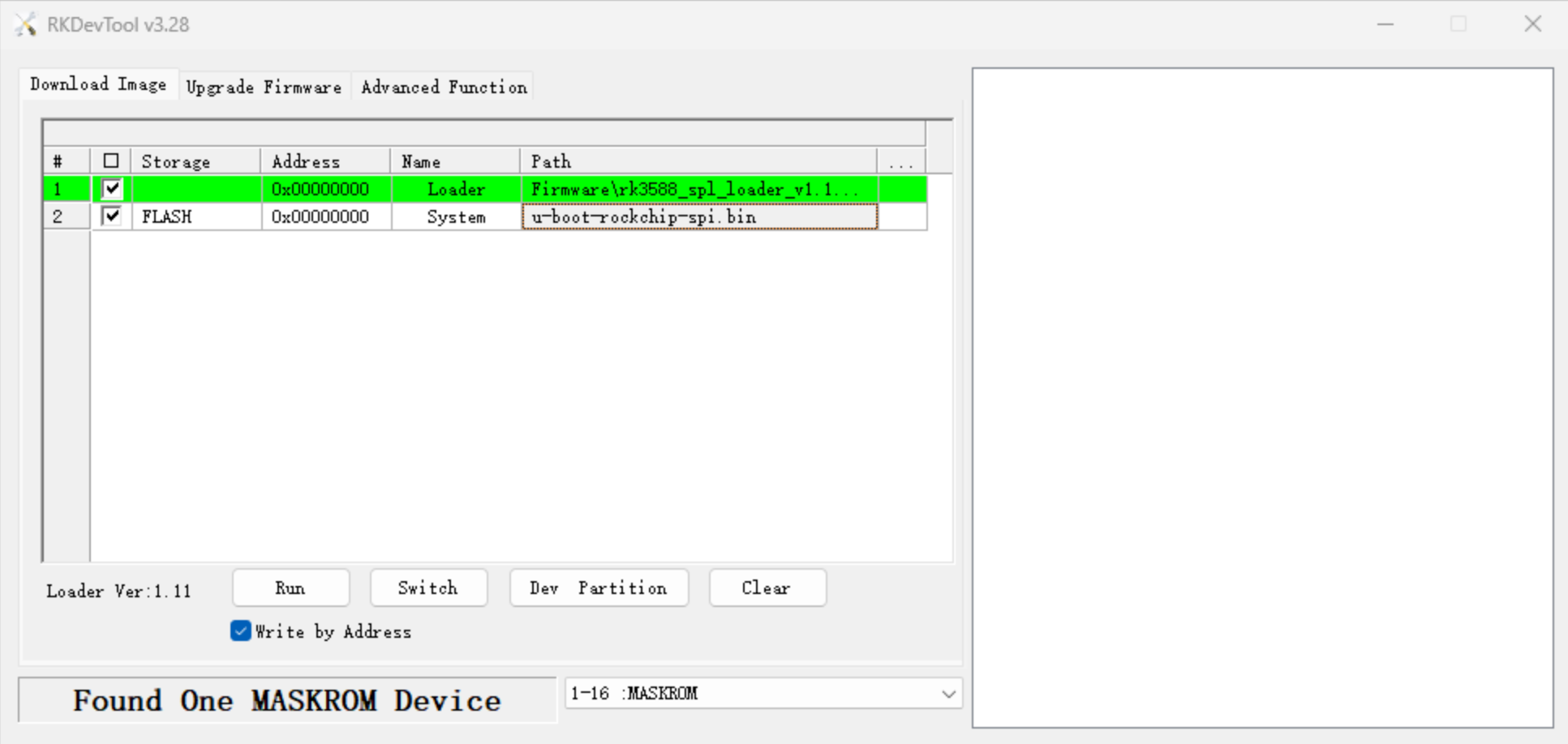
- Loader: select the Loader for the board's actual SoC. The required Loader files are stored in the Firmware directory. For example, use
.\Firmware\rk3399_loader_v1.30.130.binfor RK3399 and.\Firmware\rk3588_spl_loader_v1.10.112.binfor RK3588. The Loader must match the device SoC. - System: select the model-specific
u-boot-rockchip-spi.binusing either a relative or absolute path. In the Storage column, select Flash. Some tool versions may label this option SPI or use a similar name. - Do not configure or enable any other items.
3. Flash the image
Enable Force write by address, then click Run. The tool starts flashing and automatically reboots the device after the operation completes. Do not disconnect USB or power until the tool reports success.
If flashing fails, first verify that the Loader matches the device SoC. You can also retry with RKDevTool_Release_v2.86; use the same configuration, but do not enable Force write by address in that version.
Stop if the tool does not provide a Flash/SPI storage option or if eMMC is still selected as the target. Do not click Run in that state.
2B. Flash SPI from the device's current system
Use this method when the board already boots Linux from an SD card, eMMC, or another medium, and the kernel exposes SPI NOR as /dev/mtdblock0.
- Download the U-Boot image for the exact model. The following example is for ROCK 5B; every other model must use its own URL from the table:
curl -fL --retry 3 \
  -o /tmp/u-boot-rockchip-spi.bin \
  https://download.liveupdate.fygonas.com/arm/uboot/rock-5b/u-boot-rockchip-spi.bin
- Verify the SPI device. mtd0 in /proc/mtd must clearly identify the SPI NOR. Stop if the device is missing, the capacity is smaller than the image, or its purpose is uncertain:
cat /proc/mtd
ls -l /dev/mtd0 /dev/mtdblock0
image_size=$(stat -c %s /tmp/u-boot-rockchip-spi.bin)
flash_size=$(($(cat /sys/class/block/mtdblock0/size) * 512))
printf 'image=%s bytes, spi=%s bytes\n' "$image_size" "$flash_size"
test "$image_size" -le "$flash_size"
- Back up the existing SPI contents. Move this backup to another computer or storage that will not be affected by the procedure:
sudo dd if=/dev/mtdblock0 of="$HOME/spi-backup.bin" \
  bs=1M status=progress
sync
- Write and verify the image. Keep the device on stable power throughout the operation:
sudo dd if=/tmp/u-boot-rockchip-spi.bin of=/dev/mtdblock0 \
  bs=1M conv=fsync,notrunc status=progress
sync
sudo cmp -n "$(stat -c %s /tmp/u-boot-rockchip-spi.bin)" \
  /tmp/u-boot-rockchip-spi.bin /dev/mtdblock0
If cmp prints nothing and exits with status 0, the written bytes match:
echo $?
sudo reboot
3. Verify the NVMe boot
After the reboot, sign in to FygoOS and identify the device containing the root filesystem:
findmnt -no SOURCE /
lsblk -o NAME,TYPE,SIZE,FSTYPE,MOUNTPOINTS,MODEL
An NVMe root device usually appears as /dev/nvme0n1p.... Use the actual findmnt result as the source of truth.
If the board no longer boots, power it off and retry without the NVMe drive. If it still does not recover, enter Maskrom mode and restore SPI using the backup or the board vendor's recovery firmware.